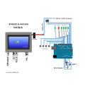
 The modbus protocol defines how communication takes place between a “master”, that manage the system, and one or more “slaves” that reply to the masters’ requests.
The protocol defines how master and slave communicate, the format of the messages exchanged between the two parties, how master and slave have to be identified and how the error messages being handled.
The theoretical limit of this protocol accounts for 247 slaves plus one master on the same bus. Conversely, the Rs485 interface can handle at maximum 31 slaves connected in the same line. However, by using a specific bridge at the end of the communication line, it is possible to extend the previous limit and use 31 more slaves.
Only the master could begin the communication, whereas the slaves are always waiting for master’s requests. The communication must be in the form of request/reply as direct query or broadcast. In the latter case, the message will be sent to every devices connected to the bus that execute the command specified in the message. The master is not able to know the result of broadcast command because the slaves do not reply to the sender.
The characteristics of modbus protocol are the following:
- Standard interface
- Parity
- Stop bit
- Rtu format (binary)
It also exists the ASCII modbus protocol, even though RTU is more efficient and widely used in industrial applications.
Messages’ format
Modbus standard defines how messages have to be encoded. In particular, the data sent or received has to be enveloped by additional informative bytes that completes and better specify the message. Both master and slaves must comply with this requirements. A modbus message must contain the following information:
- The address of the slaves that will execute the command (address 0 corresponds to broadcast and will be sent to every devices connected to the bus).
- The function code that has to be executed.
- The data (registers) to be exchanged.
- The checking error code (two bytes) calculated using CRC16 algorithm on the previous data.
When a slave device receives a message but the CRC that it calculates on data received does not corresponds to that of the message, it raise a communication error and do no execute the command, throwing away the message. Other errors might happen, such as parity check or wrong destination ID.
Connection parameters
Usually, the connection parameters adopted by devices that conform to modbus protocol (such as Arduino) are 8,N,1 namely: 8 bit data, no parity check and one stop bit.
Address
As we already know, a modbus communication transaction must be started from the master device that control the bus and only one slave is allowed to reply from its requests (or eventually no slaves reply in broadcast communication). In order to uniquely identify the receiver of the message, every slave must have an integer ID (from 1 to 247, 0 is reserved for broadcast). This address has to be added as the first byte in the messages.
Only assignments could be sent as broadcast messages because they do not require a reply from slaves.
The function code
The second byte in the modbus message represent the function code that has to be executed on the slave device. The master will be informed by the slave when the command is executed by receiving a reply message with the same function code. The function codes most frequently used are the following:
- 01: READ COIL STATUS
- 02: READ INPUT STATUS
- 03: READ HOLDING REGISTER
- 04: READ INPUT REGISTER
- 05: FORCE SINLE REGISTER
- 06: PRESET SINGLE REGISTER
- 07: READ STATUS
- 15: FORCE MULTIPLE COILS
- 16: PRESET MULTIPLE REGISTER
Error checking: CRC16
The last two bytes of the message contains the cycle redundancy check (CRC) code calculated on the previous bytes. The first byte is identified as MSB (most significant byte) whereas the second one as LSB (least significant byte). Those two bytes simply represent a 16bit value. The algorithm used for calculating the code is the CRC16.
The necessary steps for CRC16 calculation are the following:
- Load a 16bit register with value FFFh (all bits set to 1)
- Calculate the exclusive OR (XOR) between the first byte and the MSB byte. The result will be store in the same register.
- 1bit right shift the register
- If the exiting bit is 1, calculate the exclusive OR between the generating polynomial 1010000000000001 and the register.
- Repeat 8 times steps 3 and 4
- Fare l’OR esclusivo del carattere successivo con il byte superiore del registro, porre il risultato nel registro.
- Repeat steps 3 and 6 for all bytes’ message.
- The 16bit register will now contain the CRC16 code that has to be appended to the modbus message.

